

Showing posts with label Featured. Show all posts
Showing posts with label Featured. Show all posts
Thursday, 28 July 2016
Cyclops SLR Lens Spy Web Cam

Monday, 18 August 2014
uVolume T-32 OSH Park PCB Arrival

My PCB's arrived last week from OSH Park, they turned out fantastic.....
Tuesday, 25 March 2014
Dr Brown's Capacitor ESR Tester

I finally got round to making a capacitor ESR tester this week after finding a nice and simple 5 transistor version by EEVBlog member Jay_Diddy_B. Unfortunately, for me, the design was only SMD so, I decided to replicate his schematic in Eagle PCB, using a through hole component design.
Saturday, 2 February 2013
Arduino: Moppyduino M_usical Fl_oppy controller PCB
.png)
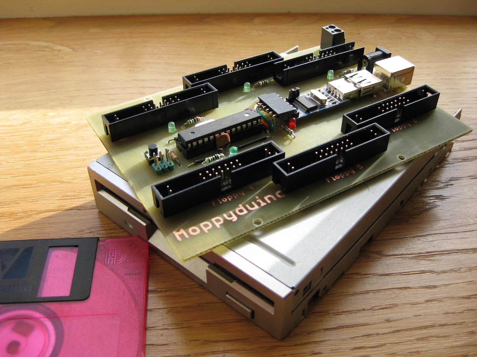
Moppyduino is a M_usical Fl_oppy controller PCB based around the Arduino. The code is provided courtesy of Sammy1Am.
If you are not familiar with the idea behind Moppy, I will give you a quick insight into world of floppy disk drive music. The basic principle involves running a JAVA IDE on the host computer, on which, MIDI format files are loaded within a JAVA applet.
When running, a serial USB link passes data between the computer and the Arduino Microcontroller on the Moppyduino. This in turn, translates the data into motion steps in various directions on the floppy drives stepper motor, producing various frequencies and vibrations.
In the case of the Moppyduino, I opted for a nice balance of just 6 channels, which equates to 6 floppy drives. Depending on the pin count of the Microcontroller, up to 18 floppy drives can be connected!
The toner used in the ML-2165 works great for making PCBs. There was however,one problem I did run into with this cheap laser printer, the paper alignment due to the nature of the toner transfer method. Typically, you have to run the sheet through the printer multiple times to get a nice thick layer of toner.The first layer tends to stick firmly to the paper or laser OHP transparency film (which i prefer to use).
I will reveal more on the ML-2165 printer alignment tweak in another article.
.jpeg)
When I designed the PCB, I wanted to make it as easy as possible for others to produce a floppy music based project without messing around with a lot of wiring. So, I opted to use standard floppy cables and 34 pin IDC sockets. All the configuration is done on the PCB so, it's pretty plug and play :)
A lot of unnecessary pins were removed from the 34 way floppy IDC PCB sockets to ease construction and also to make removal of the cable less stressful for the PCB.
Regulated power for the drives is supplied from a 5 volt switched mode power brick (USB HUB PSU) with a 2.4 Amp rating, power consumption for running 6 floppy drives is around 2 Amps (peak) at 5 volts, Averaging 1.3 amps, With an idle of 0.20 Amps.

On the board is a bare bones Arduino using a USB to TTL adapter to receive serial data from the PC
A USB to TTL breakout adapter such as the one below would be more suitable to incorporate into the PCB design, it would allow for a less complicated and more compact layout. At the time of the prototype design I used what I had at to hand, Hence the need for a USB A and B socket back to back.
If you have to choose between the CP2102 and the PL2303 chipset go for the CP2102 as this has driver support for Windows 8. The PL2303 only has support for Windows 8 in the HX revision

The size of the PCB was dictated by the actual size of a floppy drive, therefore, the PCB mounting holes align with the M3 screw holes on the bottom of all standard 3.5" floppy disk drives.

The video below shows the whole process from the PC to the working Moppyduino including, the toner transfer,etching the circuit board and soldering of components.
.jpeg)
Some of the more "eagle eyed" readers may have noticed that the drives are installed upside down! This was intentional.The Moppyduino PCB mounts to the existing M3 mount holes on the underside of standard drives.I just happen to like seeing all the channel activity LEDs flash :)
If you would like to build or improve on my design which is a starting point (see the download link below).
Please leave a link in the comments section with your creations :)
Moppyduino PCB Design Files Download
Samsung ML-2165 Printer Alignment Tweak
I will reveal more on the ML-2165 printer alignment tweak in another article.
.jpeg)
When I designed the PCB, I wanted to make it as easy as possible for others to produce a floppy music based project without messing around with a lot of wiring. So, I opted to use standard floppy cables and 34 pin IDC sockets. All the configuration is done on the PCB so, it's pretty plug and play :)
A lot of unnecessary pins were removed from the 34 way floppy IDC PCB sockets to ease construction and also to make removal of the cable less stressful for the PCB.
Regulated power for the drives is supplied from a 5 volt switched mode power brick (USB HUB PSU) with a 2.4 Amp rating, power consumption for running 6 floppy drives is around 2 Amps (peak) at 5 volts, Averaging 1.3 amps, With an idle of 0.20 Amps.

On the board is a bare bones Arduino using a USB to TTL adapter to receive serial data from the PC
A USB to TTL breakout adapter such as the one below would be more suitable to incorporate into the PCB design, it would allow for a less complicated and more compact layout. At the time of the prototype design I used what I had at to hand, Hence the need for a USB A and B socket back to back.
If you have to choose between the CP2102 and the PL2303 chipset go for the CP2102 as this has driver support for Windows 8. The PL2303 only has support for Windows 8 in the HX revision

The size of the PCB was dictated by the actual size of a floppy drive, therefore, the PCB mounting holes align with the M3 screw holes on the bottom of all standard 3.5" floppy disk drives.

The video below shows the whole process from the PC to the working Moppyduino including, the toner transfer,etching the circuit board and soldering of components.
Corian Open Rack Enclosure
.jpeg)


Some of the more "eagle eyed" readers may have noticed that the drives are installed upside down! This was intentional.The Moppyduino PCB mounts to the existing M3 mount holes on the underside of standard drives.I just happen to like seeing all the channel activity LEDs flash :)
If you would like to build or improve on my design which is a starting point (see the download link below).
Please leave a link in the comments section with your creations :)
Moppyduino PCB Design Files Download
Samsung ML-2165 Printer Alignment Tweak
Subscribe to:
Posts (Atom)